Ad Clicks : Ad Views : Ad Clicks : Ad Views : Ad Clicks : Ad Views : Ad Clicks : Ad Views :
Oh Snap!

It looks like you're using an adblocker. Adblockers make us sad. We use ads to keep our content happy and free. If you like what we are doing please consider supporting us by whitelisting our website. You can report badly-behaved ads by clicking/tapping the nearby 'Advertisement' X text.

SOLIDWORKS – Shell and Beam Modeling in FEA

/

Release date:2018, September 20

Author:Tony Abbey

Skill level:Beginner

Language:English

Exercise files:Yes

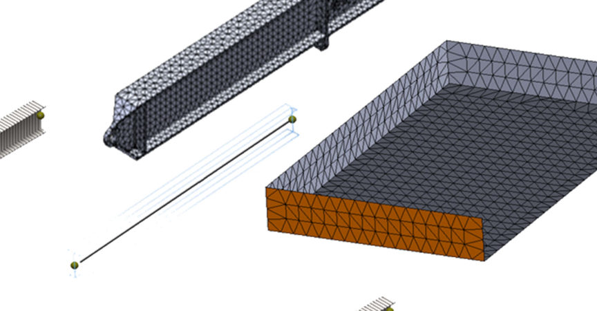
Much of CAD design uses 3D elements for finite element analysis (FEA) simulation. However, sometimes thin-walled or frame-like structures dominate. In these cases, shell (2D) and beam (1D) elements can represent designs more effectively. Across all industries, as much as 50% of the design of major engineering projects fall into these categories.

In this course, instructor Tony Abbey explains how to work with shell and beam models in SOLIDWORKS. Learn when to use shell, beam, and specialized truss elements; understand the fundamentals of modeling with them; and find out how to mesh, postprocess, and model components with these tools. Tony shows how to set up and run these FEA simulations to test the integrity of your designs and view results such as stress, force, and displacement.

Topics include:
Modeling beams and trusses
Using weldments
Modeling shells
Using surfaces
Using solid bodies
Using sheet-metal bodies
Setting up and running FEA simulations

Table of Contents

Introduction
Shell and beam elements in SOLIDWORKS 49s
What you should know 1m 6s
Using the exercise files 1m 1s
1. Idealization with Shells and Beams
What are shells, beams, and trusses? 3m 56s
2. Focusing on Trusses
Truss modeling background 1m 51s
Truss model: 3D geometry setup 4m 20s
Truss model: 3D geometry results 3m 23s
Truss model: Weldments setup 4m 49s
Truss model: Weldments results 2m 57s
Truss: Beam differences 4m 56s
3. Focusing on Beams
Beam modeling background 2m 33s
Benchmark beam model: Pinned joints 4m 55s
Benchmark beam model: Welded joints 4m 18s
Loaded beam model: Geometry setup 4m 32s
Loaded beam model: Load boundary conditions (LBC) setup 5m 9s
Loaded beam model: Results 3m 28s
4. Focusing on Shells
Shell modeling background 3m 20s
Shell from surface setup 3m 19s
Shell from surface LBC and run 4m 17s
Shell from geometry setup 4m 44s
Shell from geometry LBC and run 4m 2s
Sheet metal setup 3m 33s
Sheet metal run 3m 47s
Conclusion
Next steps 1m 32s

  • Facebook
  • Twitter
  • Google+
  • Linkedin
  • Pinterest

Leave a Comment

Your email address will not be published. Required fields are marked *